
On haul out, Windstar would leak plenty plenty water from the keel/hull joint, even when the bilges were bone dry (which they usually are) and she showed evidence of the infamous C&C smile, where as with many boats the joint opens up a bit over time. The PO had actually attempted a repair of this. A little online investigation revealed that water can gets into the putty-filled section of the keel stub, where it can eventually do what water often does. I figured I'd better at least get Windstar's keel rebedded, so I contacted a yard for a quote. Here is the rather alarming response:
From: Nick Bailey
Sent: Thursday, October 01, 2015 2:50 PM
To: SYER David
Subject: RE: Estimate to re-bed keel, C&C33MKii.
Sent: Thursday, October 01, 2015 2:50 PM
To: SYER David
Subject: RE: Estimate to re-bed keel, C&C33MKii.
Hi Dave,
Thanks for your request for estimate...
If all your boat needs is refastening the keel as outlined below it will cost somewhere around $4000 including labour, materials, travelift fee & tax. That amount is approximate & could vary 20% in either direction. It also assumes the boat is already here on the hard at the Port Credit Harbour Marina but we can arrange winter storage for you here at a competitive rate.
However, based on our long experience repairing C&C's, in particular the 33 Mk II, 35 Mk III, & the 41, all of which have the ballast attached to the hull at the end of a very deep keel sump, there may be more serious structural issues involved, particularly if the boat has been aground at any point in its life. The key indicator of more serious issues are exterior stress cracks (sometimes obvious, sometimes subtle) at the radius where the fin meets the hull, particularly at the leading & trailing edges. Other signs of trouble are cracks or delamination where the interior structural grid meets the keel sump, delaminated tabbing at the bottom of the main bulkhead port & stb, or signs that the mast step is sagging.
If in doubt, have an experienced surveyor familiar with these issues look at the boat. i.e. Bill Provis, 416-801-5527; Peter McGuire 416-809-2186; or Wallace Gouk 416-526-3845
If you need more information feel free to give me a call.
Nick Bailey
Bristol Marine Ltd.
Well... Windstar did in fact have some stress cracks at the leading edge of the keel stub, and, there was the water. Fortunately, she did not exhibit any of the other symptoms. Yet. So... What to do?
Some photos of the subject area. You can see that the forward two keelbolts penetrate a space filled with polyester-based putty.


 |
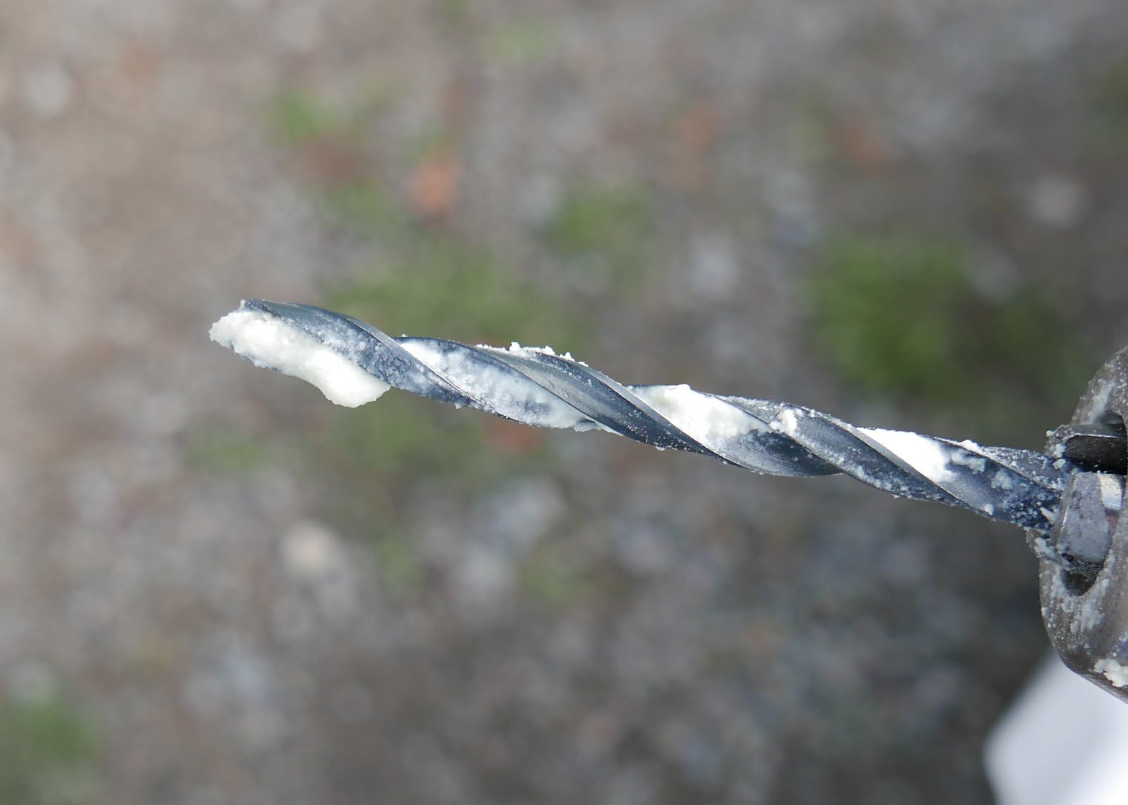
| My test holes revealed waterlogged whitish hardened putty inside. |

So.... What to do about it?
See below from Doug A who dealt with more advanced issues with his 35iii
"Dave / Joe,
The boat in question is a 1985 C&C 35-III which I purchased from the
original owner in the spring of 2013. While the mast step didn't look like
it had sagged, I thought I needed to improve the load distribution. So I
built a longer step for the original mast step to sit on. The mast step
enhancement was made with a 7" X 18 " aluminum structural channel with a
1/2" X 5 1/2" X 17" aluminum plate inside it. The original mast step sits on
top of the 1/2" plate. The channel dumps all the rain water to the bilge.
Raised the mast about 7/8" but not a big deal.
The keel bolts were torqued to spec with the exception of the forward bolt
under the mast. It just didn't want to tighten like the other bolts.
During the 2014 four race fall series, the wind averaged 17 to 22 knots, so
the boat was well heeled on each weather leg. After each race I was pumping
about two gallons of water from the forward cavity under the mast step using
a inspection hole I had made. When the boat was hauled, the smile had
reappeared and was seeping stinky water. I drilled a 1/4 hole into the keel
cavity on the leading edge of the fiberglass just above the lead and about 8
oz of foul water drained out. Additionally the forward keel bolt had lost
what torque it had. I was convinced at that point that the high density fill
C&C used below the mast was breaking down just as it had on my friends the
33 II. So after talking with other 35 III owners with similar issues, I
decided to excavate."
>> snip
Others report that in addition to being unable to torque the keelbolt to spec, they also cannot tighten their rigging as the mast step keeps compressing.
Here are photos of the mast step area in the 33. Workmanship not exactly inspiring, but OTOH, it seems to be perfectly intact.


See how the liner has been trimmed to allow the step to settle? this was done at the factory.


Look closely. to the lower right is a piece of marine plywood, roughly cut on one edge, which supported the starboard half the mast step, and under the mast step, a blob of putty which supported the port side of the mast step.


Nice and clean. the area around the bolts was slightly concave, but certainly not fractured or badly distorted. A large aluminmum pad bedded on filled epoxy would distribute the bolt loads much better than the washers.
So, you can imagine what happens.
A 1" bolt torqued to 300 ft/lbs exerts a tremendous amount of clamping force. On the first bolt, the mast step spreads this load somewhat but on the second keel bolt, standard fender washes are used to distribute this load. See below.

http://www.engineersedge.com/calculators/torque_calc.htm
When torqued, the keel bolts exert 18000lbs compression on the fibreglass top of the keel stub and if that deflects, on the putty beneath. The mast and rig exerts its own additional load, as do hard groundings. If the putty has shrunk, is crushed, damaged or deteriorated, it compresses to some extent. You run aground, things get jarred, maybe fracture a bit. Torque is lost, things move, the mast step sinks a little, the smile opens, more water enters, etc.... You re-torque, things compress.... Etc.
When it hits this stage, the typical repair is major:
- Cutting out any interior parts which hinder access
- opening the keel stub,
- removing all of the putty (hardened polyester resin, aka "bog". basically cheap marine bondo),
- ideally adding some structure to take the compression lead of the bolts,
- refilling the cavity with... something,
- repairing the glass that was cut for access.
- reestablishing some sort of structural integrity as this is a major stress-bearing region of the boat.
- Replacing the interior.
A pro repair of this type would certainly exceed $10,000. (Bristol Marine has developed a slick repair that involves drilling a hole coaxial with the keel bolts, and replacing the putty removed with a fiberglass compression post. this minimizes much of the work described above. I have no idea what they charge for this.)
On the other hand....a boat that had not yet exhibited any signs of failure or significant deterioration could be perfectly fine. Keep the water out, improve the load bearing surfaces to better distribute the compression, and it would likely be fine for another 30 years.
Windstar had no significant signs of structural degradation, although the fiberglass supporting the second keelbolt had sunk a bit. After a lot of thought and discussion with others, I elected to simply do a thorough job of reinforcing the mast step area, and anywhere else subjected to the keel bolt torque. I feel that the factory could have done better than simply using washers, and I think most builders skimp in this.
I would hate to have you go through the same experience. [he had invested considerable time in a reinforcement strategy, only to have to remove it and fully excavate the keel stub] Especially after doing glass work under the mast step making a much more difficult job if you decide to do some digging. Think about it. I know that we have different boats, but a good friend of mine at the club has a 84 C&C 33 who warned me about the problem. He had excavated his cavity several years prior for the same reason. Which is why I knew what to expect.
Again, I can't thank Doug enough for the time he took to share the details of his own excellent repair, and as a sounding board for my own.
I thought also about eventually having to sell the boat and I did not want to be in a position of having to be less than transparent about what may have been a latent issue. Life's too short for that.

My home away from home. That vac was totally inadequate, and I needed my huge shop vac.

The patient prepped - I elected to cut out the side of the settee for access. I will replace the panel, but leave the oval slot you can see for ventilation.

Here is a "core sample" of the top of the keel stub, in the area where the bolts bear. Glass is 3/8 thick. A bit thicker under the forward keel bolt.

You can see the top of the keel stub cut away, and the first few holes drilled into the putty with a spade bit. The stub is 24" deep, around 7" wide and around 24" long. I ended up drilling holes about 3" deep, then using a 4"crowbar bashed into the hole to lever and break away the putty. Repeat for two full weekends...

A few inches down and a long way to go. See the black. moldy fault lines, and the piles of rubble accumulating on the deck. You can almost see the starbord side of the keel box, which had seperated from the putty block. This is where the water would accumulate, though there were cracks throughout, and the putty itself was damp throughout even the pristine solid parts. Talc-filled I think. Ugly, but I don't think it was deteriorating badly - certainly not like I've heard from others.

Are we there yet?

After getting the keel box excavated I had to figure out how to make this repair permanent. Which material to fill with? How to manage the compression loads? There have been several approaches. Some, like Doug A have made stainless posts sleeved over the keel bolts, some have installed posts adjacent to the keel bolts, and perhaps most elegant is Bristol Marine's approach where they do not excavate the keel stub anymoe, but have developed a tool which bores a hole into the keel stub co-axial with the keel bolt, and extracts the filler. they then install a built up fibreglass post over the keel bolt in that hole. By the way, Nick at Bristol was also very helpful in this. It was clear this would be a DIY job, and he offered a great deal of encouragement and advice. (and offered me a job...lol) Thanks Nick!
So, I made a couple of very sturdy compression posts, laid up over 1.25" ABS pipe.

Work in process.

Posts were cut at the correct angle and had sheet fibreglass feet attached with massive poxy fillets, and these were then set into epoxy on the bottom of the keel box. More glass filled epoxy was used to secure the posts in place. Killer stuff.
Ready for filling....
After consultation with others I elected tous polyester laminating resin, (AOC Altek HDA-596) with colloidal silica and long strand chopped glass. I was able to mix 1 gal at a time, and learned to time the pour so that each gallon could use the considerable heat from the previous gallon's cure to hasten its own cure. I mixed 1% catalyst to resin. I mixed the resin with 1% catalyst and was very lucky to have warm weather into December.The entire job took 15 US gallons of resin and about 6kg of chopped glass (plus a bunch of scrap fabric and other glass I had kicking around. This weights approximately 150lb, the same as what I removed (slightly more I would guess...) but is much more solid, and should absorb less water.
 |
| Yes. Messy |
 |
| Resin heavily loaded with glass. |
 |
| Trial fitting |
Ground to slightly undersized, with beveled edges, and fitted flush at the same height as built.

Epoxied in place with a dime for luck - Canadian of course, the Bluenose visible.
the worst is over!


Partway there


Here's how the parts created in the previous post were installed. They were bedded in very thick, glass-loaded epoxy, making a massive (relatively) dead-flat deck for the mast step and foundation to take the compression loads from the keel bolts.


And this chapter will close with a "before" image!
A beautiful solution, better than new. But if the fill material was beginning to break down, rather than excavate, could one not let it dry out, and pour epoxy resin over everything, to fill all gaps and seal it up pretty much like
ReplyDeletea rock? Even if not 100% dry, there are epoxies that will cure in the presence of moisture.
Years later I reply - sorry! No, I don’t think so, the cracks are narrow and wet and a proxy is generally too viscous to flow into spaces that small. Also, it is very likely the keel bolts would end up glued in place. Not a good situation….
DeleteAny photos of the completed project? Getting ready to do this job myself here soon. Was thinking of creating my own tool/s to drill coaxial along the keel bolt. My concern with this is not knowing the exact depth. Won't know what I'm into until I drill some holes like you did into the side of the stub and the top. I'll find out soon enough.
ReplyDelete