Saturday, 27 July 2019

Deck fill core removal and reinforcement.

Dealing with Deck fills.

Water ingress over time will penetrate a cored laminate, and eventually cause rot, delamination and failure.   It is generally  recommended that the core be removed in these areas and replaced with solid glass, leaving the core itself un-penetrated by fasteners or fittings.   Failing that, holes or exposed core should at least be well sealed with epoxy to prevent water ingress.   Windstar, as with many older production yachts, had simply had the deck fittings installed directly through the cored area of the deck, with no precautions taken.

On Windstar, the fresh water deck fill and pump out fittings, though installed through balsa-cored areas of the deck, and had been well bedded with butyl tape.   After over 30 years, the fittings remained watertight and the deck core dry and sound.   While I was doing work that exposed this part of the deck,  I took the opportunity to take the precautions I describe above.


First project, the fresh water fill.

Below is an image of the deck fill penetration, which is through both the deck and liner.   This is a real pain as it is necessary to remove the liner to inspect or work on the underside of the deck.   Since I had elected to remove the liner to strengthen the deck to bulkhead joint anyway, it made sense to deal with the deck fill as well.  See that project here.  

After removing the liner, it was necessary to remove the core in a radius around the deck fill opening.  This was done with an allen key chucked in a drill, working from above.   Crude but very effective, it removes the core from approximately 1” around the existing hole.     The pics should tell the story, but essentially the shaft of the key registers against the existing hole and the spinning key removes the core.  Hold the drill with both hands!   

To replace the balsa, I made a circular plug the same thickness as the core.  This consists of 3 discs of scrap laminate, stacked and epoxied together.  A bimetal holesaw chucked in a drill press was used the cut the discs, and the material was from scrap panels cut from Windstar when installing hatches.

 That puck was fitted into the prepared area, well bedded in glass-filled epoxy putty, and the entire area was then glassed over.  The work is done wet-on-wet (really, wet-on-B-stage) to ensure the best possible integrity.   The holes were then bored for the new deck fitting from above.

And the fitting installed, (well-bedded with butyl tape of course) into a  a solid fibreglass section of the deck.   


Second project, different approach, the pump-out fitting.

For most situations, this is probably a better method of dealing with this task than I describe in the first section of this page. 
As before, the balsa core was removed using a cordless drill and allen key.   In this case the Allen key was ground to the length required to remove only enough core to comfortably clear the screws of the replacement deck fill.  The interior skin on the C&C is thick enough that it remained intact, which is a great help.

Using two hole saws and interior fibreglass retained from this project to make an interior  reinforcing/backing  washer for the fitting.


The gap created between the deck and inner skin was filled with epoxy/glass putty.  The deck fill,  which was wrapped with polyester packing tape and heavily waxed, with its backing plate, was then inserted from below.  the remaining space and the screw holes were then filled with more glass/epoxy putty, and smoothed with a gloved finger.


The deck was then wiped down with an acetone-soaked rag.  Once the epoxy cured, the fitting was pressed out.   The opening was sanded to soften its edges and remove any "flash", and the fitting was reinstalled from above and the new screw holes drilled.  The fit is quite precise, as you might imagine.   
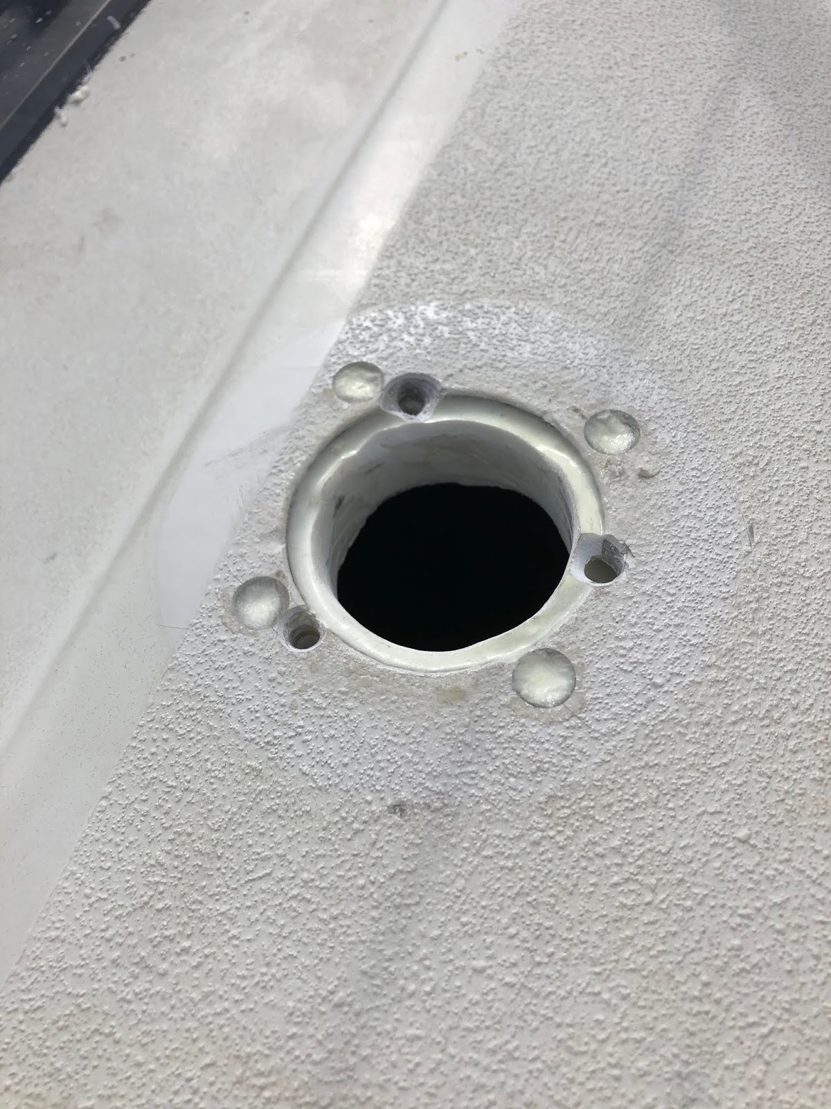

Because the previous holes were countersunk, they were not hidden by the new, smaller fitting.  I elected to make a UHMW (starboard) pad to hide these.   I used the same concentric holesaw technique above, and radiused the edges using a router table.

And the fitting and its screws were all bedded with butyl.
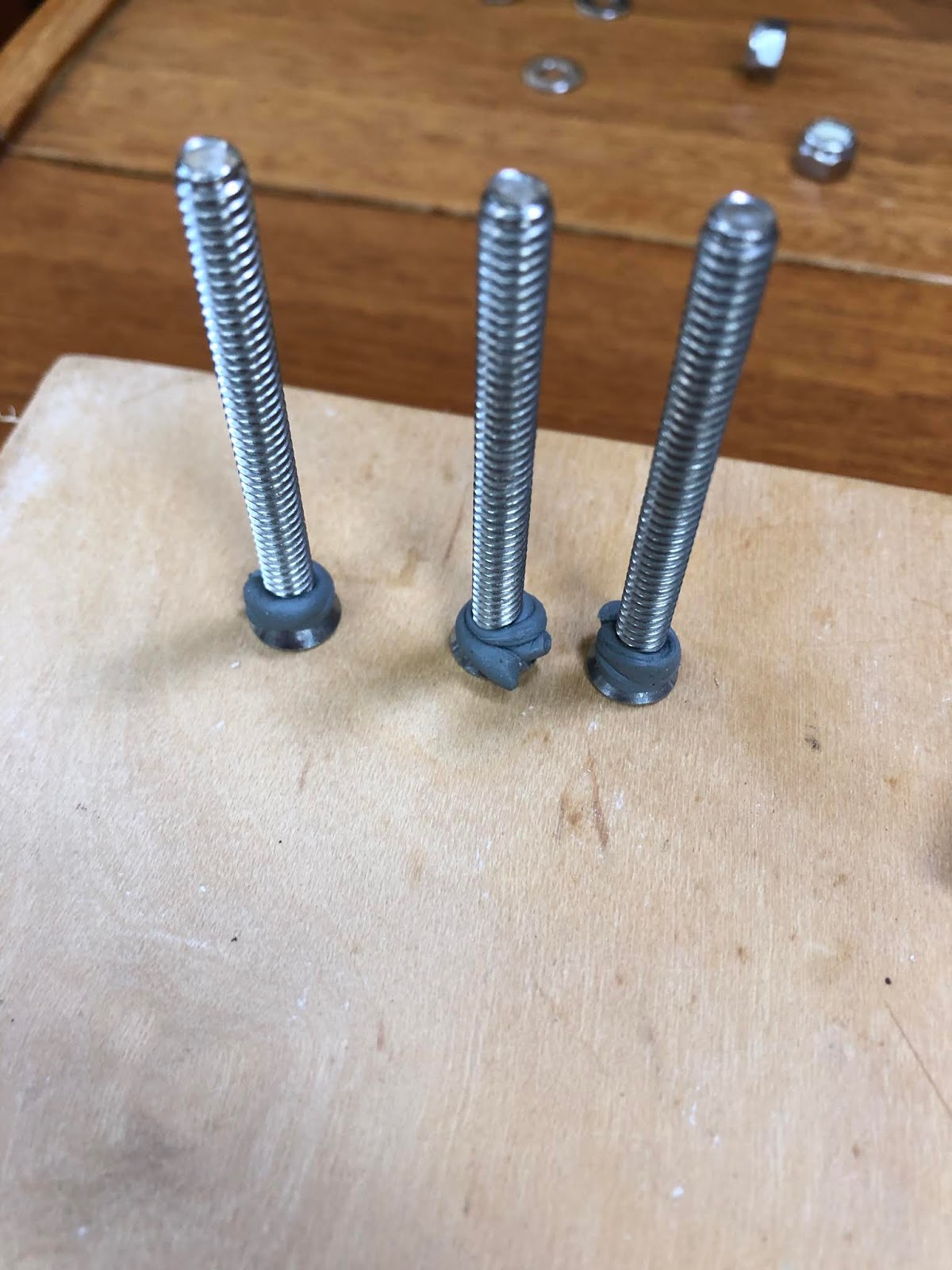


Diesel fill will be replaced at some point.


Bulkhead/Deck Reinforcement at the Hanging Locker - no more creaking.

When Windstar was being sailed you could hear creaking as the bulkhead “worked” the in overhead liner.   You could replicate this noise by firmly pushing and pulling the hand-hold at the top corner of the locker.   Furthermore, some very minor deck deflection could be detected by bouncing hard above the area.    (the deck does not yield to my 200lb elsewhere.)

Windstar is hull number 61, and the bulkhead at the aft end of the hanging locker is well tabbed to the hull, but was not secured to the deck as it is in some other 33-2s.    The bulkhead simply rests in a groove in the overhead liner, and can therefore "work" as the boat flexes.

To remedy this, it was necessary to to remove the liner inside the hanging locker, and then verify that  the balsa core and laminate were intact, especially around the fresh water fill, (which was inaccessible under the liner) and then to securely tab the deck to the bulkhead.

The photos aren’t great but they tell the story.   The water fill, locker top, hanger rod, etc were all removed, and the liner was carefully trimmed out using the Fein multitool and a bimetal blade.   The balsa core and laminate were all perfectly intact, however the putty blob used to secure the deck to the liner was cracked and the bond had failed.

Below you can see the interior of the locker, fore and aft, and can see how the boat was constructed in this area, particularly in the first photo, and how the bulkhead simply rests (restlessly) against the liner.


Below are the same views with the liner removed.   Note that I retained the inboard edge of the liner as the teak trim above the top of the hanging locker is secured there.    You can see the putty blobs used throughout the boat to bond various non-structural parts together.   You can also see that I removed the core around the deck fill.  improving the integrity of the deck around the deck fills is covered in another post.

putty removed and mostly prepped for all epoxy/glass work.

The original putty (which had cracked at the aft bulkhead) was carefully cut out and the narrow space cleaned out as best as possible, and the all surfaces were sanded and carefully prepped.The next images show the putty removed and the space between the deck and liner filled with glass filled epoxy, and next a radiused fillet of the same material added.


 And finally, the glass/epoxy tabbing was pre-laminated on sheets of waxed paper and carefully placed into to the still-wet epoxy fillets and bulkhead.  This sort of work is best done wet-on-wet as it assures a solid bond between stages.  Pics below show the layers of biaxial stitch mat laid up on a sheet of waxed paper, and then installed.


Am happy to report that the creaking has disappeared, the deck is now quite stiff.

Worth noting is that some 33-2s seem to have had the liner removed and these bulkheads tabbed in place at the factory, so I would expect that owners may have made the factory aware of this issue in early models. 

Here are some photos of Bruno L.'s 1987 33-2


To keep this in perspective, Windstar had  had seen no ill-effects or failures from this early construction method after over 30 years of use.  So, while I'm glad I did it, it was not a major structural concern.

Monday, 27 August 2018

Another storage addition.... Hatch in Nav desk footwell.

The 33-2 is not a huge boat, and this becomes evident very quickly if even a modest cruise is planned.  This is compounded by the production boat reality of the cost associated with adding access hatches and making some of the more oddly shaped bits of interior volume accesssible.   Case in point, the space under the nav station footwell.  Pics are self explanatory.
Am pleased with this addition - the volume available is surprising, and I like the idea of any opportunity to increase airflow throughout the boat.

Hatch is made by Viking products.  


Th

Thursday, 28 June 2018

MAST STEP CHOCKS AND SHIMS

Mast step chocks and shims.


More fun with Shock cord- Bimini Frame


More fun with Shock cord- Bimini Frame


Had been annoyed for awhile with the arrangement for securing the bimini fore and aft.


As you can see, Windstar has three pieces of canvas, the dodger, the bimini, and a connector spanning the two.   The conector can only be used in harbour, as the main sheet track is in the cockpit.   As it is, the main sheet fouls the dodger slightly when running.
It's a good setup for this boat however it requires slacking and re-tensioning  the lines securing the bimini fore and aft in order to attach the connector canvas.
A perfect use for shock cord!
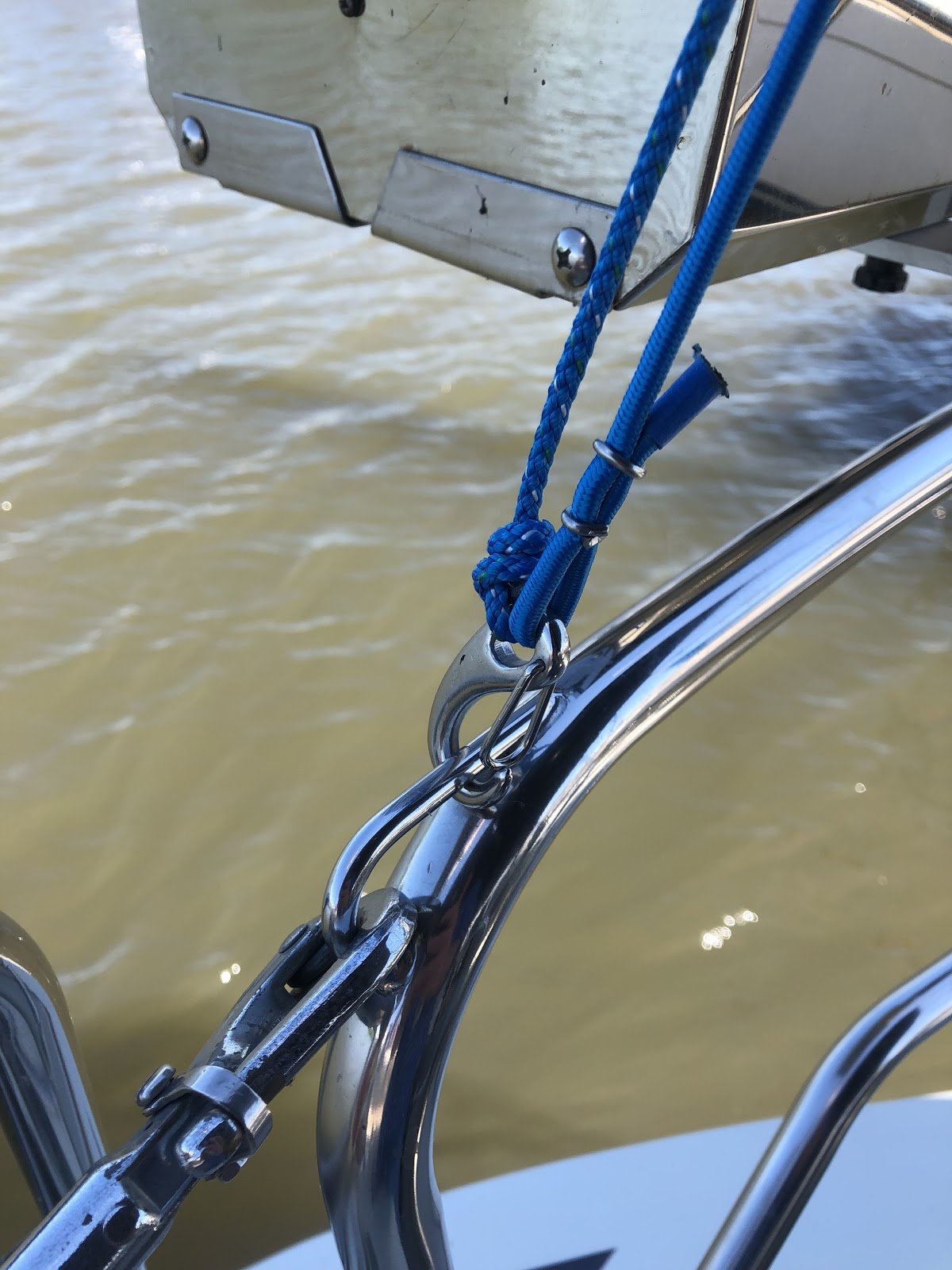
After puzzling this out a bit I positioned two fixed-length lines led forward.  these define the limit of rearward tilt of the bimini frame in the absence of the connector.  Below, port side.


I then added shock cord to pull the frame aft against those two fixed lines, and further added two lines parallel to the shock cord that can be tensioned with a rolling hitch.


The shock cord provides enough tension to spring-load the bimini against the connector or the forward lines, and the adjustable parallel lines define a limit of forward travel.
Works great and the bimini can now be pulled forward to operate the connector zippers, and it springs back into place when released.

Tuesday, 4 July 2017

LED interior lighting

Original fixture
Have been grappling with the replacement of the OEM square fixtures in Windstar, and was having trouble finding LED replacements that are:

  • similar in footprint
  • have a switch on board
  • have a night lighting option
  • are affordable.
  • not more cheap/cheesy than the originals.
  • Have space in the housing for the bulky butt splices used to connect OEM fixture to the boat's wiring.
 The fixture below was suggested by a fellow C&C mailing list member, he installed these as direct replacements.  His wife was made happy.  Meets all my criteria except for red night lighting.  So, I decided to purchase a bulk bag of red LEDs and see if I couldn't modify the fixture.

https://www.princessauto.com/en/detail/7-1-2-in-x-5-in-led-interior-vehicle-light/A-p8488686e


Princess Auto, C$14.99


 The LEDs were mounted in snug fitting holes arranged around the perimeter of the light source, and the micro switch was installed at the same and as the supplied switch.  The leads were taped over when done.  It is not necessary to glue in the LEDs.

It works fine.  The SPDT switch supplied with the fixture permits wiring the LED toggle switch so that it is powered only when the fixture is off.   In other words you can't use both at the same time.   The orange/white wire is +12vdc, the black is to ground.


Modified fixture with LEDs, micro toggle switch, and resistors.
Mediocre Photos requiring no explanation, other than the hazy lens which was wet sanded to reduce glare.


The following website wizard simplifies the LED circuit design.  You input your parameters, it outputs a schematic.   http://led.linear1.org/led.wiz

All done for around C$20 per fixture!


Sunday, 11 June 2017

How to drain the ice box?

Here is a photo of Windstar's ice box drain pump.  It is a Beckson SiphonMate hand pump, mounted in a bracket below  counter.   The inlet is connected to the ice box drain, the outlet to a length of hose which is not connected to anything, but  is long enough to reach the sink.


When Windstar showed up, the self priming SiphonMate was not.  Replacing it with a new one solved the problem.   It is a simple, effective approach, however I would prefer a drain that was direct plumbed into an overboard drain rather than relying on a coiled length of hose.   Pretty low on the list of issues, and mainly,  I post this for those who would like to see the stock installation of the SiphonMate.

A recent discussion on the C&C mailing list was started by an owner with a blocked ice box drain hose, which left me puzzled.  Drain where?  The bilge?  Nasty.  Turns out there were others with the same plumbing, (a prior owners' fix?) and others who had addressed this in different ways.

Below is Lee's solution, repurposing a seawater pump and faucet.   I expect the seawater pump was a dealer option.   (Windstar has only one footpump, from the freshwater tank.)

 "I have no need to have lake water at the sink so we repurposed the pump to drain the ice box. The hose goes from bottom of ice box to foot pump at foot of sink. This pump used to pull lake water in an dispense in the sink."


Saturday, 27 May 2017

Cockpit VHF speaker without butchery

One item on my long list of things to improve was to ensure I could hear the VHF from the helm.  I have an aversion to cutting or drilling holes in a boat, and will do whatever I can to solve a problem without doing so. (drilling holes I mean!)   In this case, the solution was fairly easy - mount the speaker in the lid of an existing access cover.
The hole was cut using a flywheel-type adjustable circle cutter on a drill press.   I clamped two pieces of MDF in the drillpress (stacked) and cut a hole  equal to the cover plate's diameter through the first piece.  Removing the cut out created a fixture in which the cover could be placed, already centred under the drill press chuck.  I then re-adjusted the cutter to the correct diameter for the speaker hole, firmly clamped the cover in its fixture, then slowly bored the second, smaller hole through the cover.    Not for the faint-hearted, but it worked fine, and any lack of concentricty is not noticeable..
 The sound  is very loud and clear, the ICOM M506 VHF has plenty of power to drive this inexpensive Polyplanar speaker.


Sunday, 21 May 2017

Port side settee stowage access


A 9600 lb racer-cruiser has limited stowage for even short cruises with more than 2 people.
One of the things I dislike about the 33-2 is the way the port side fold-out double berth impedes access to the only large stowage area in the boat.  In the pretty drawings, they don't show that the under the starboard settee resides only the fresh water tank, under the V-berth resides only the holding tank, and under half of the quarter berth resides one small locker and two batteries in a difficult to access locker.     The port settee is available for stowage, BUT the drop leaf table must be dropped, the seat cushions removed, and the berth extension folded out before you can lift the covers to access the stowage.  A nuisance!   Also, it's all one big compartment so the reserve beer and wine can crush the reserve potato chips.     (Apparently the water tank was moved to this side on later production years.)  

I wanted more convenient access to this settee locker, so I decided to add some hatches as you see in the photo.  I chose Tempress 1115 (11" X 15") slam hatches.  There are others, but these are:   "as functional as they are stylish"

Stylish!

See below for photos, fairly self explanatory.  I used a bimetal holesaw, and my fein multimaster with a circular bimetal blade.   Next step will be a simple barrier between the two compartments.

In future the chips will meet the beer only at the time and place of my choosing!


Sunday, 14 May 2017

Navigation light - cable deterioration

The SJ 16/2 cable used to connect the bow and stern running lights in Windstar has not stood the test of time.  This cable is intended as portable cordage, and has rubber-insulated conductors inside a neoprene jacket.  The conductors'  insulation is crumbling and just waiting to create a short and tripped breaker. The prince of darkness lurks...  Will post pics, it's toast, and it's now gone.  

The PVC insulation used throughout the rest of the boat is fine, it's just the length from the light, through the pulpit/pushpit to the bullet connectors below deck, where the lights connect to the harness.  (the cables in the mast were fine also, except for some wear and tear at the base of the mast.   I rewired the mast in '17 anyway.)

The neoprene cable jacket is likely in much better condition than the conductors' insulation, therefore the condition of the conductors is not evident when simply inspecting the cable from the outside.  Check the conductors themselves where they are exposed.