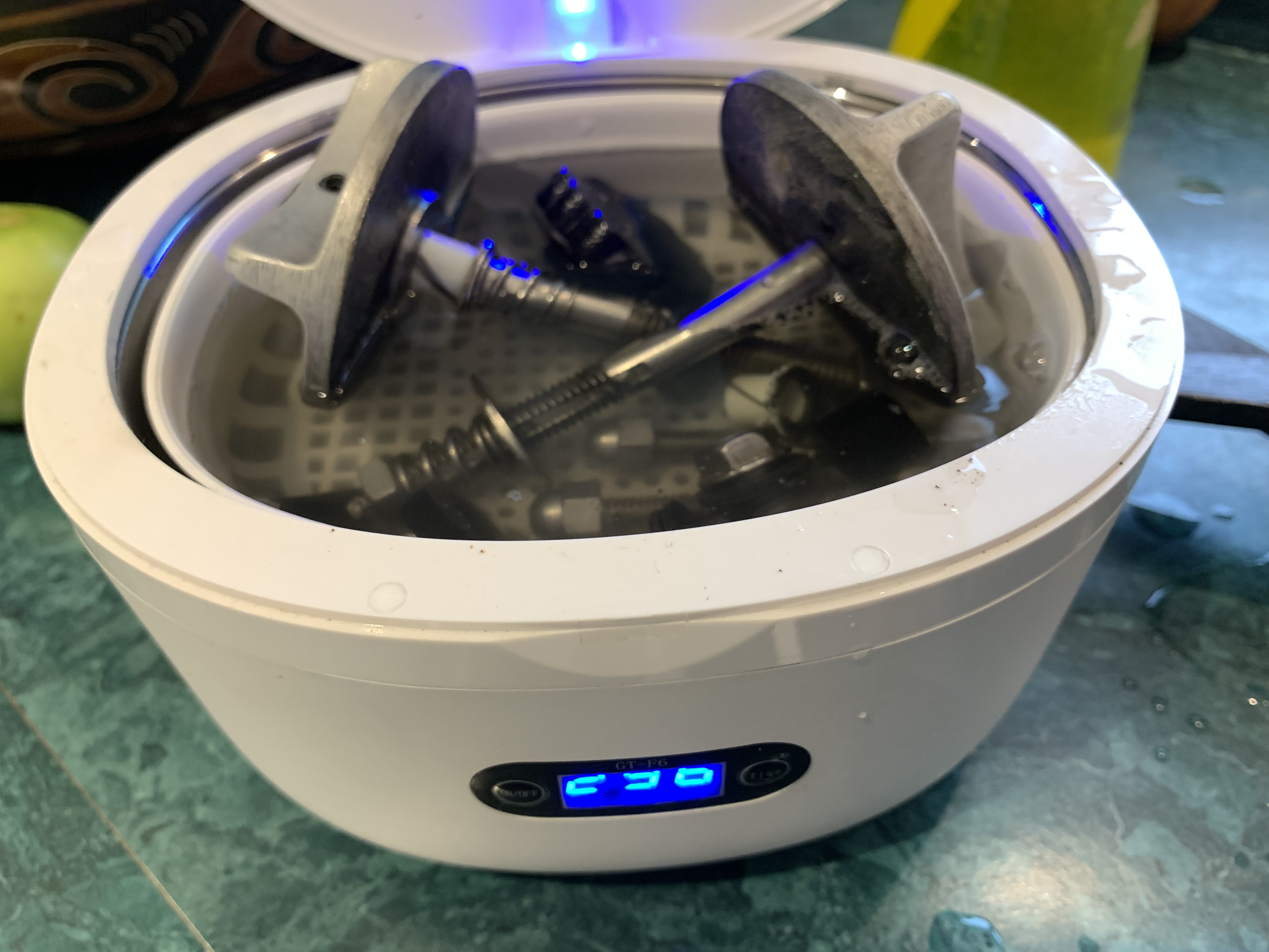
Update, April 2023- 10 years later I noticed some clutch slippage so re-honed the cones and replaced the seals. Pics and hasty write up below. It is really helpful to make a fixture by hole-sawing a 2x6 to hold the shaft in place.
You’ll need a puller, pin punch, appropriate sockets, lapping compound torque wrench, RTV gasket compound, solvent and a tub for parts washing, aerosol parts cleaner, brushes. An arbour mounted wire brush and buffer is handy for cleaning and polishing the sealing surface on the output flange.
You definitely want the yanmar shop manual. Read the notes!
One thing it doesn’t say is to switch the output shaft nuts- inside for outside - and you’ll get a fresh flange for staking the nut to the shaft.
I can now do this in less than 2 hours with around $30 in parts and materials.
When done, Remember to adjust the shift linkage cover per the manual prior to reinstalling.
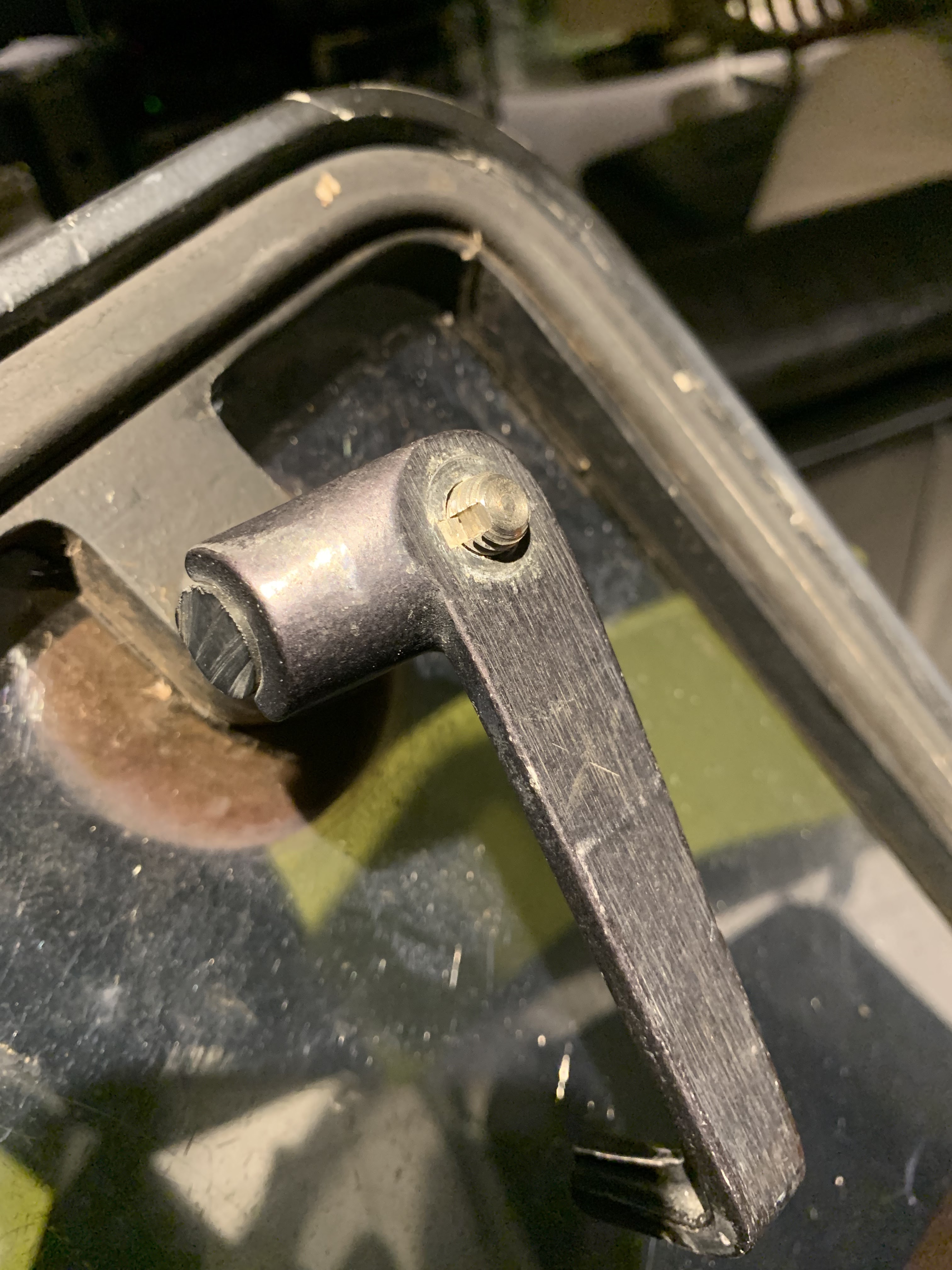
Before starting, note the position of the shift lever on its shaft. It is not keyed, and it’s position impacts the position of the control lever.
As removed. make sure the transmission is clean and the oil has been drained.
First step, remove the dipstick, gear selector and output shaft flange. You need to bolt a bar to the the flange for this to prevent it turning. don't forget that the 27mm flange nut and the identical internal shaft nut has a reverse thread.
Second step, remove the hex screws securing the transmission case to the bellhousing. They are all the same length. You will remove the output shaft (big one with the gear on the left) and leave the others in place.
Note that there's no gasket, just a very thin layer of RTV sealant. Clean the mating surfaces carefully, and dont let any crud fall into the transmission housing.
you can see here how the shift lever mechanism engages the groove in the clutch cone. It moves the clutch cone into either the forward or reverse gear, where the cone is received by its mate (inside the gear) and either slips, or doesn't.
The flange is lagged onto a 2X6" fixture to serve as a stand for the next steps.
Shaft inverted and held in place for briefly working from the other side. No torque needed, so this jury rig is fine.
Puller pulling.
Gear stack being disassembled. The yanmar manual covers this. Have a seperate tray, labelled, each for forward and reverse parts.
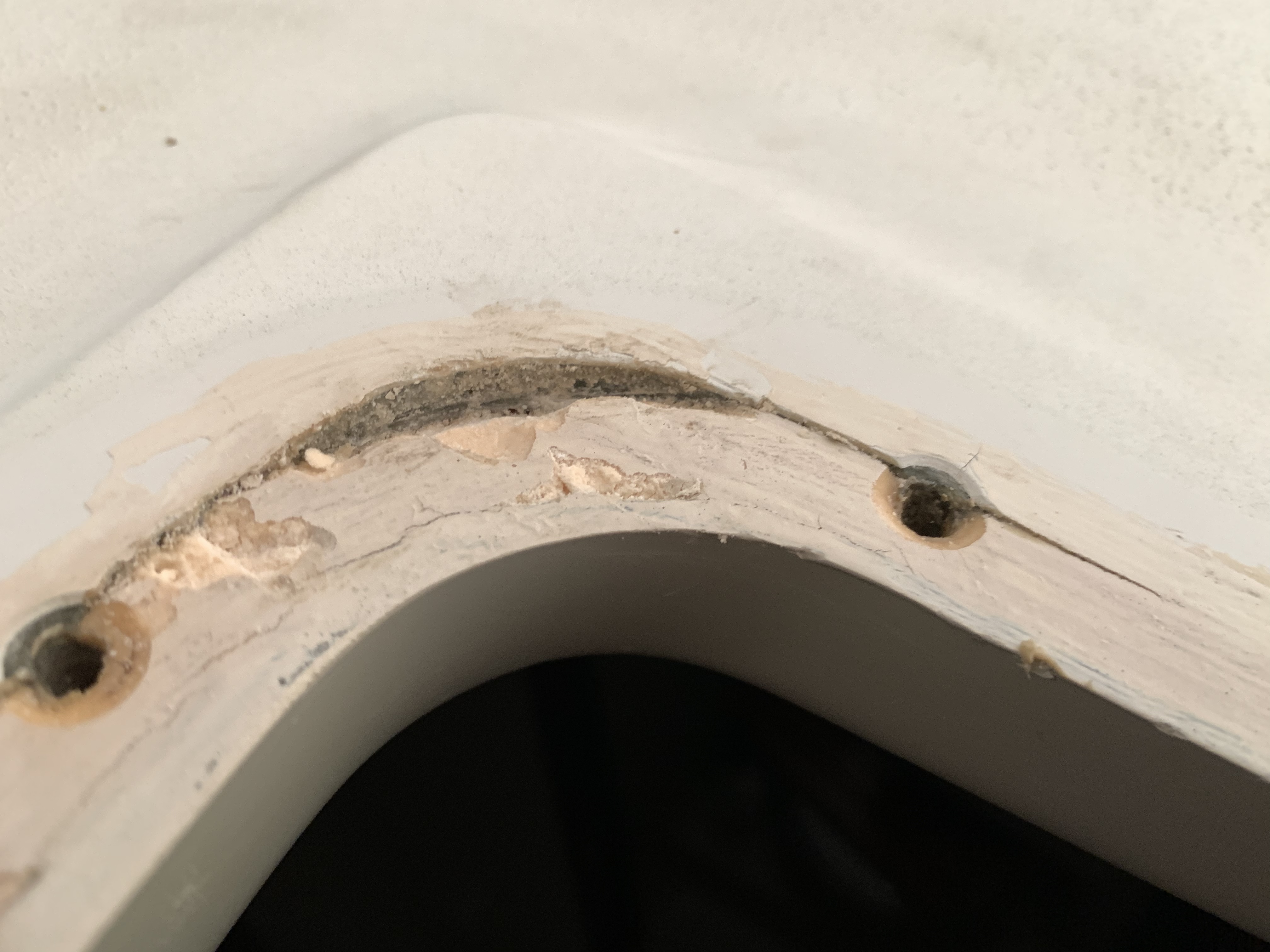
you can see the glazed interior of the forward gear. Note also two small centre punch marks I made on the forward side of the clutch cone. The forward gear itself is marked with an "F". see below.
Abrasive compound has been applied. then mate the parts and rotate back and forth. wipe it out and repeat. do it again.
Then clean it reallly really well. The deglazed cone is clearly visble on the left, below.
Cleaner than clean and drying. Get all of the grit off. Then do it again with clean solvent.
Reassembly.
output flange cleaned with sealing surface polished, then painted. Don’t paint the flat surface that mates to the shaft flange.
As mentioned above - don’t forget to adjust the shifter cover per the instructions in the manual. I missed this once on a friend’s transmission and I think it caused the come to glaze again prematurely. (Sorry Terry).
10 years prior…..
Windstar suffered a worsening vibration - much more extreme than that really - in forward gear. It started intermittently but progressed to the point that the boat was unusable.
After paying a pro to misdiagnose shaft, engine mounts and alignment as causes for a terrible banging vibration I did some homework online and utimately fixed it myself over a weekend for about $30. Not for the mechanically inept, but not difficult either. The specifics are hard to find via google, so I copied the post I found at the time and pasted it below. Unfortunately I can neither crediit nor thank the original author.
The Post (not mine)
The
gearbox is quite a small unit and it is fixed to the
engine by 8 bolts around the bell housing, 4 bolts on the prop shaft and releasing the control cable, easing the prop shaft gland we were able to slide the prop shaft back a couple of inches sufficient to allow the
gearbox to move back and be lifted out. Not having the right tools on board I was able to put the gearbox into a carrier bag and take home with me.
Cleaning an area on the workshop bench, I drained the
oil, removed the 4 bolts that held the control lever in place and removed it. The gearbox is accessed by removing the 8 bolts holding the bell housing to the gearbox, the jointing was just liquid cement so having removed the bell housing I could now see inside the gearbox. You need to be careful to protect the
seals at each end, there are 3 shafts an input shaft, an intermediate shaft and the one that we are interested in the output shaft, which is recognised by being the largest and has a locknut on each end. Note: these nuts are left handed threads.
You need to clear the locking tab and using a long handle socket or torque wrench to remove the nuts. You will then need a puller to remove the roller bearings and collar (2) and the bearing inner
race and collar (2). You should then be able to lay out the whole shaft on to a nice clean surface, clean the individual components and inspect for damage or wear. The main area’s to look at are the bearings and the drive cone. Having said earlier that the reverse
gear seemed ok, I was hoping to reverse the drive cone if possible as I felt this was not as important as the forward
gear but I found that the gearbox had been opened up previously and that the cone was worn both sides, however there was some grooving left on the cone with a possibility of reclaiming the contact surface.
The cone is moved in and out of the large gearing by the selector mechanism, the tapered surface of both forward and reverse gear were very shiny, possibly were they had been slipping ? I could not find any referance to this in the manual, so I decided to lap the tapered surface’s with some fine grinding paste ( I was surprised what a difference this made ) When fitting the tapered surfaces together they now locked 100 % and I felt that I had done the right thing.
All
parts were then meticulously cleaned before starting to reassemble. You will need a piece of tube to knock the bearings and collars back on. If you have been careful you can reuse the
seals and the locknuts, when fitted these need to be torqued up to approx 10 kg/m or 70 ft/lbs, check that all is ok before using liquid
sealant and refitting the bell housing. Note: A Large vice is very helpful for stripping down and reassembling and don’t forget to relock the locknuts.
Before fitting the control mechanism, use the aperture as an
inspection hole to see that the gears are turning and that the cone moves forward and backwards, you should now be able to fit the control mechanism, Check the O ring is ok and that the shifter which actually locates in the centre of the cone is set to its lowest point (it is possible to be 180 degrees out), loosely fit the 4 bolts, hand tight and fit the control lever to the correct angle.
Note : the bolts holding this plate are over size, allowing for movement to be able to adjust the control lever, so as you can set the same amount of lever movement forwards and backwards, when this is correct you can tighten the 4 bolts.
Before refitting the gearbox, check that the damper plate which is fitted to the flywheel is all ok, then you should be ready to fit the gearbox, lightly grease the spline on the input shaft and slide the gearbox back into position, fit and tighten the 8 bolts, you can then adjust and fit the control cable, put in the required amount of gear oil and secure the filler
plug. Slide back the prop shaft and secure the 4 bolts, you should then be in a position to carry out operational tests. At this stage I found that I wanted to readjust the control lever movement and I found it was just as easy to remove the gearbox,
lift it into the
cockpit and do it rather than struggle in the engine locker. My friend then carried out some tests and found a big improvement, so how long had the cone been slipping ? I quite enjoyed doing the job although as you get older it is more difficult to get in and out of the engine compartments, a bottle of whiskey changed hands which was very nice and it saved my friend putting
money into someone else’s kitty.


.jpeg)