Sunday 28 July 2019

Where to keep the Flares?

Flare storage box and mounting bracket


A small project to ensure the flares can be quickly found, while still being out of the way.   

I scoured Amazon for boxes and found this - a perfect fit.   I then made a fitted bracket and installed it in a visible but out-of-the-way place.  Will add a bright and easy-to-read label.

The bracket is made of 1/4" acrylic plastic, bent using a strip heater.   You can see that there is a doubling of thickness on the back of the bracket to permit the strap to pass.  That doubling was done by fusing two layers of acrylic together with a solvent called methylene chloride.  I have used this  stuff many times without incident but this time I unknowingly splashed some on my leg, the result being some deeply-blistered chemical burns that I became increasingly aware of some hours later.   (these are taking weeks to heal)

It's a easy to be cavalier about safety...  please be careful.


Tackling the Refrigerator

Improving Windstar's Refrigeration


As Windstar is currently outfitted, refrigeration is by far the largest consumer of electricity at anchor, limiting the time she can be powered by her 230ah house bank.   As purchased, there were other functional issues, covered below.  The condenser/evaporator unit is made by Novakool, p/n LT-200, made in 1999.

Update August 15, 2020

The new lid is finished and has been in use for a month or so.   One piece, no hinges.  It works fine and makes cleaning much easier.  I don't think there's a lot more that can be done to improve the 33-2's refrigeration in the existing footprint.  The teak fiddle and the laminate top (Wilsonart "Putty") is a very close match with the original interior.

Updated - June 10, 2020


The following solved the frosting and energy consumption problems as well as is practical within the stock footprint, so next I turned to replacing the countertop with a single piece with teak fiddle to match the original.  Basically laminate was epoxied to both sides of a plywood sheet, it was trimmed to size with a flush-cut router bit, and a teak fiddle created to match the originals.  I did not counterbore and plug the screw holes as the screws are out of sight anyway, and I prefer ease of refinishing to ultimate cosmetic perfection.

Update Sept 2 2019

Windstar's refrigeration has been significantly improved, and after many weeks has not required defrosting.   Food remains cold much longer than before when the fridge is off, and when running, the thermostat can now be left on setting 1, and food will not spoil.
Initially, post-upgrade, I was disappointed that the unit still ran 75-80% of the time.   This was during a mid-summer heat wave, with temperatures in the 90s and high humidity.   I was then unaware of the non-linear relationship between ambient temperature and fridge temperature, and have observed (bur not measured) that in more moderate temperatures, the compressor might run 20% of the time, or less.    I recall reading but cannot now locate a chart which showed that the fridge will run 3X longer per hour at ambinent 90 deg F than at 70 deg F.
I am pleased with the improvement, and doubt that there is much more that can be done to significantly improve the performance of the fridge within the limitations of the interior furniture.  Would be interested to know if there are further improvements that could be realized.

Also see this post on how to drain the ice box.

Original posts - July 2019  


Windstar's fridge worked, but never did work well.   The evaporator iced up quickly, it seemed to run constantly, would freeze in parts and be warm in others.  It needed constant defrosting which filled the bottom with water... in short, a nuisance. 
My first tack was to email NovaKool asking about the expected performance of their refrigeration unit and after some patient and very helpful questioning about the installation, was informed that the unit was likely functioning correctly, and that until the box could be sealed it would always frost up quickly and simply wouldn't function properly.
The 33-2 has a two-section lid which is theoretically convenient, but is both poorly insulated and impossible to seal where the two halves abutted.
So.   I puzzled over various too-clever solutions to seal the two halves of a split lid, and in the end decided to start with a simple, single-piece insulated lid that could be made to seal against the flange at the top of the fridge.

Making the lid.

The project started with a thin sheet of fiberglass laminate glass laid up on a large piece of waxed plate glass.  One sheet of mat between two layers of cloth, made with polyester laminating resin was enough, and one side is of course glassy flat.   Once cured, it was trimmed very approximately to size.  More detail on making fibreglass parts can be found here.


I had puzzled over insulating materials for awhile and in the end stopped puzzling and used sheet styrene from Home Depot.   Inexpensive and easy to work with, it does not have the highest possible R value, and is not compatible with polyester resin, so any "wet" work would require different adhesives.  Perfect is the enemy of better.
I laminated two 1" thick sheets using 3m 77 contact adhesive, (great stuff!) then cut it to size on the table saw, with each cut edge beveled a few degrees..


Once cut, it was then glued to the fiberglass sheet, again using 3m 77.   The corners were then gently radiused in preparation for sheathing with glass cloth and epoxy resin.  This type of foam cuts, machines and sands easily, making it great for forms for composite work with epoxy and 'glass. 


The cloth was laid on its bias (the weave diagonal to the corners) so it would wet out and drape more easily and I'm  happy to report no issues or voids.   Some strategic reinforcement around the flange and on the corners and its done.  Very light.


This single piece replaces the two ugly panels below.

Upgrading the Interior of the Fridge

In for a penny, in for a pound, I decided also to make a removable shelf, and to reinstall the evaporator box, as it had been really poorly done and needed to be lowered to clear my new, thicker lid.  
These spacers are made of two layers of 1/4" acrylic. 


Shabby shelf.


Ugly wire shelf.
The new one started with a sheet....


Bent with a strip heater and an ad hoc bench fixture.


The insulated portion of the lid in place.  You can see in the photo above, that strip of counter at the back is intact.  After some thought, I elected to remove this as you can see in the photo below.  


 It works!  I can now set the thermostat at its lowest setting and the temp stabilizes at +1 deg C, with little evidence of frosting after 24 hours. 
So far so good.

Upgrading the Box


This was something I'd been puzzling for awhile; essentially how I might supplement the 1+" foam insulation used by the factory.   In the end, I kept it simple and bought a can of spray foam and extended the nozzle with some straws donated by a local Wendy's, and supplemented the outboard side and bottom of the box.   Access is a challenge and there is really no practical way to add insulation elsewhere from the outside, so it is necessary to accept less than ideal insulation.   (though improved)


While working inside the box, I noticed a gap between the ice box mold and the countertop  (hull liner) mold.  The box is a separate unit, installed below the countertop.)   I caulked this gap with silicone around the entire perimeter of the fridge.

While testing, I also noticed condensation on top of the fridge, along its aft edge.   This 2" deep , 22" wide flange is uninsulated, as are the 1.25" wide flanges along each side.  This is a significant shortcoming, second to the unsealable lid, with around 80 square inches with no insulation at all.   (!) 

Insulating the Flanges 

Turns out I had just enough 2" thick off-cuts from the lid insulation board to make insulating "bars" that could be siliconed in place to better insulate the top. 

First, they had to be cut and radiused.   The stuff is easy to work.


Ready for epoxy.

Then, coated with epoxy, and fibreglass cloth set into the wet epoxy for durability.  Once cured, sanded and trimmed, they were painted then glued and caulked in place with silicone.  


Yanmar 2gm20f fuel seepage

Update


A look at the Yanmar service manual revealed that the assembly in question has an o-ring at its base, which would be the logical source of the leak.  (#2 in the exploded drawing.)


Thankfully, this turned out to be the problem, and after removing several coolant hoses for access, the repair was straightforward.   Unsurprisingly, after 30 years of heat, diesel and pressure, both O-rings were somewhat hardened and no longer round in section.     Total cost to repair less than $10.   There are springs under pressure that are released in this situation however they don't leap to freedom and a reasonable amount of care is all that's required.  There was a small amount of corrosion evident in the o-ring groove, and i cleaned this and greased the area and the fitting's threads, for benefit of Windstar's future owner who will doubtless deal with this again in 2058.

This made a surprising difference in the livability of Windstar's interior.  Doesn't take much diesel to perfume the entire living space.

Update


 - used ye olde Baby powder trick and the leak is at the base of one of the injector lines .  See below.
This basically means degreasing the area.   Once the engine is basically clean (hopefully it always is...) , use aerosol brake parts cleaner to remove any residual diesel film.   This stuff is effective, leaves no residue and dries quickly.  When the talcum is applied it is white and dry and it will be immediately evident when any fluid dampens it as you can see in the photo.  Thus, if you are watching closely you can determine the source of the leak, even if it quickly flows elsewhere.  Handy.


Windstar’s engine is seeping in the area of the high pressure fuel pump.   Diesel collects around the serial number shown in the photo below and slowly migrates down the starboard side of the engine.

Any suggestions as to source and remedy?

Many thanks!


33-2 Ventilation Strategies

Update

Pretty pleased with these improvements overall, and I think that I would make ventilation a priority on a next boat, and resolve any issues sooner.  (I waited several years to deal with this on Windstar.)

The Nicro day and night vent seems to stop, then start again if I cycle the switch. Not sure if that's a result of a reset mode when discharged or not.   Also, I have read several posts from owners who are repairing these things when the motors fail, and are using a similar motor used in 12v toys, and available inexpensively on Amazon.   My next boat wont have one of these.  While I like the principle, it seems a lot like an expensive toy, and for me at least, one of the pleasures of sailing is knowing that the boat is tough and simple, and that modifications and upgrades are well-reasoned and soundly engineered.  I think a few rugged, heavily built passive vents are the way to go.   Oh well.

The 33-2 needs better ventilation...

As on most production boats.

The 33-2 was designed without any consideration of ventilation or air movement (other than opening its hatches).   This is not ideal, and I decided to start with two approaches.
  

Adding a V-Berth Dorade Vent


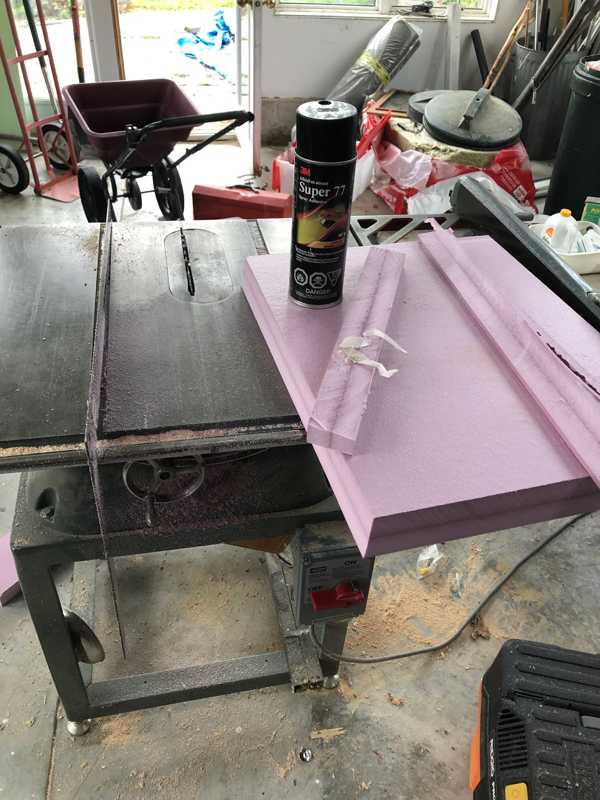
First improvement was to copy a feature of the CS36T; the use of  the anchor locker as a dorade box.   This is done by installing a cowl vent in its hatch, and cutting vent openings in the bulkhead at the foot of the v-berth.

I used a nicro/marinco 3" low-profile cowl vent and its associated hardware for both the deck hatch and vent trim, as this would standardize on snap-in closure plates. 

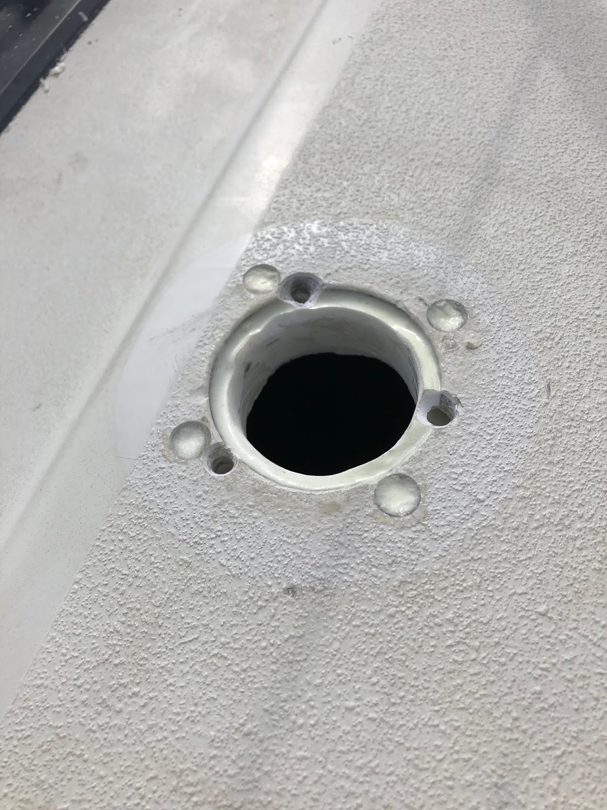
A hole saw was used to cut all 3 holes.   As the cowl vent is not an overly stressed area, (and I'm a bit lazy) I did not remove the balsa core from the hatch lid, instead taking care to drill the holes oversized, epoxy all exposed surfaces, and to tighten the nuts and screws carefully so as not to crush the core.    I used butyl tape to carefully seal the plate to the deck to further protect the core.  The cut edges of the interior bulkhead were also coated with epoxy should they ever encounter water.
The approach works and there is improved air movement as a result.


Adding a Day and Night Solar vent.


The second step to increasing air movement was to add a day/night solar vent.  (a gadget I’m not quite sold on.)  
Choosing a location is a challenge on the 33-2 as these vents are quite bulky and have the potential to snag lines, plus the deck is quite cambered in most areas, making installation impossible without building and fitting a base. I had considered adding this to the fore-hatch however even the smaller sized vent is quite high in profile, and I was warned that the slope in the hatch might contribute to leaks.  Furthermore, many of the passive vents available have closure mechanisms that protrude into the cabin, and would in my view have been unsightly on the inside hatch, as well as providing yet another place to bash my head.
I elected to install the vent on the centerline of the coach roof, forward of the opening hatch, with the interior trim penetrating through what had been a frosted acrylic lens for a fluorescent fixture, which needed replacement.   This was much preferred to cutting a hole in both the deck and the liner and the lens modifications were combined with a much-needed lighting upgrade.   There is just enough space here to install the 3” unit on the flat of the deck, though I drilled for a 4” should I later decide to install one.   (it will overhang at the forward edge slightly) 
Installation was straightforward, and I was pleased to see that the deck is cored with quality marine ply in this area.  
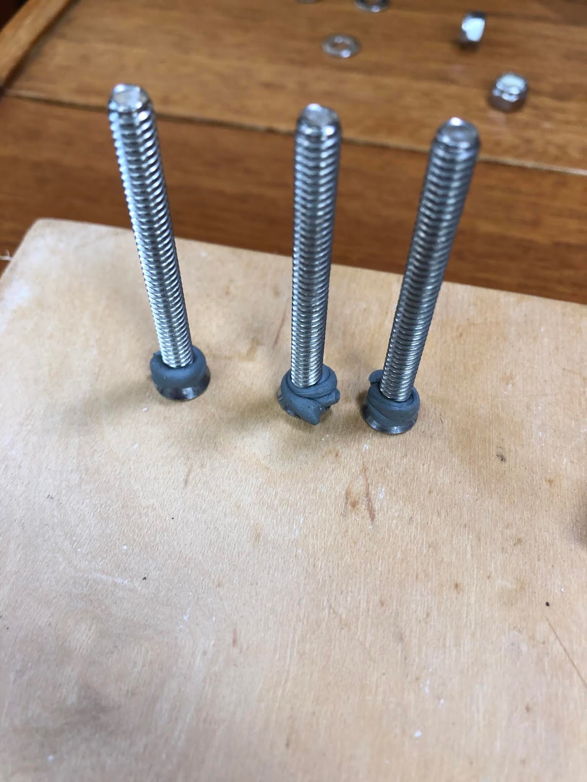
As usual, holes were drilled oversize, epoxy was used to seal the core, butyl tape to seal the fitting, and machine screws/nuts were used instead of wood screws.
The lighting is an improvement though these fixtures are too bright when relaxing below, and I have acquired a dimmer to address this.   The advantage of course is that since the existing plexiglass lens was used and the liner was not drilled or modified, the lighting can be changed at any time by making a new plexiglass panel.  3w LED fixtures are from Amazon.


The boat is now noticeably fresher when first opened. 
It is surprising how little air movement is required to really improve the health of the interior.  As an example, our first boat (an early 70's Venture 222) suffered from condensation and mildew above its v-berth until I installed a small passive dome vent in that area.   Was amazed that this yard-sale item solved the problem.
Overall these solutions have worked well.   That said, I am not convinced that the day and night vent is worthwhile or could stand up an any sort of demanding situation.  It is threaded into a thin plastic collar, will need batteries replaced, and will require jury-rigged solutions when the hobby-quality motor or switch fails.    Ok for an RV maybe, but a really sturdy, offshore-quality passive vent might be a better investment.  I'm kinda glad i located it where it is unlikely to be kicked, snagged or stepped on, and when it fails I may replace with something more in keeping with the quality of the rest of the boat.

Saturday 27 July 2019

Deck fill core removal and reinforcement.

Dealing with Deck fills.

Water ingress over time will penetrate a cored laminate, and eventually cause rot, delamination and failure.   It is generally  recommended that the core be removed in these areas and replaced with solid glass, leaving the core itself un-penetrated by fasteners or fittings.   Failing that, holes or exposed core should at least be well sealed with epoxy to prevent water ingress.   Windstar, as with many older production yachts, had simply had the deck fittings installed directly through the cored area of the deck, with no precautions taken.

On Windstar, the fresh water deck fill and pump out fittings, though installed through balsa-cored areas of the deck, and had been well bedded with butyl tape.   After over 30 years, the fittings remained watertight and the deck core dry and sound.   While I was doing work that exposed this part of the deck,  I took the opportunity to take the precautions I describe above.


First project, the fresh water fill.

Below is an image of the deck fill penetration, which is through both the deck and liner.   This is a real pain as it is necessary to remove the liner to inspect or work on the underside of the deck.   Since I had elected to remove the liner to strengthen the deck to bulkhead joint anyway, it made sense to deal with the deck fill as well.  See that project here.  

After removing the liner, it was necessary to remove the core in a radius around the deck fill opening.  This was done with an allen key chucked in a drill, working from above.   Crude but very effective, it removes the core from approximately 1” around the existing hole.     The pics should tell the story, but essentially the shaft of the key registers against the existing hole and the spinning key removes the core.  Hold the drill with both hands!   

To replace the balsa, I made a circular plug the same thickness as the core.  This consists of 3 discs of scrap laminate, stacked and epoxied together.  A bimetal holesaw chucked in a drill press was used the cut the discs, and the material was from scrap panels cut from Windstar when installing hatches.

 That puck was fitted into the prepared area, well bedded in glass-filled epoxy putty, and the entire area was then glassed over.  The work is done wet-on-wet (really, wet-on-B-stage) to ensure the best possible integrity.   The holes were then bored for the new deck fitting from above.

And the fitting installed, (well-bedded with butyl tape of course) into a  a solid fibreglass section of the deck.   


Second project, different approach, the pump-out fitting.

For most situations, this is probably a better method of dealing with this task than I describe in the first section of this page. 
As before, the balsa core was removed using a cordless drill and allen key.   In this case the Allen key was ground to the length required to remove only enough core to comfortably clear the screws of the replacement deck fill.  The interior skin on the C&C is thick enough that it remained intact, which is a great help.

Using two hole saws and interior fibreglass retained from this project to make an interior  reinforcing/backing  washer for the fitting.


The gap created between the deck and inner skin was filled with epoxy/glass putty.  The deck fill,  which was wrapped with polyester packing tape and heavily waxed, with its backing plate, was then inserted from below.  the remaining space and the screw holes were then filled with more glass/epoxy putty, and smoothed with a gloved finger.


The deck was then wiped down with an acetone-soaked rag.  Once the epoxy cured, the fitting was pressed out.   The opening was sanded to soften its edges and remove any "flash", and the fitting was reinstalled from above and the new screw holes drilled.  The fit is quite precise, as you might imagine.   


Because the previous holes were countersunk, they were not hidden by the new, smaller fitting.  I elected to make a UHMW (starboard) pad to hide these.   I used the same concentric holesaw technique above, and radiused the edges using a router table.

And the fitting and its screws were all bedded with butyl.


Diesel fill will be replaced at some point.