Sunday 18 April 2021

Rudder barrier coat, bottom paint


 The VC-TAR on Windstar’s bottom has stood up for many years. It’s still resilient, and though cracking somewhat, and I decided to tackle stripping the rudder to see what might be required to do the entire bottom at some point.  

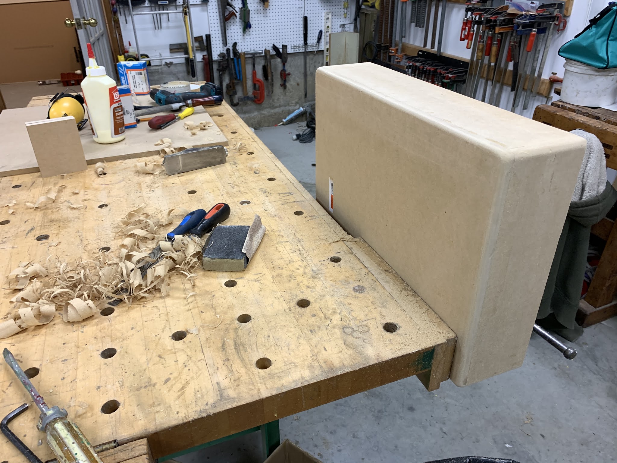
It is difficult to remove.  Good stuff I guess.   It is rubbery and clogs grinding discs and sandpaper, and resists even a stiff wire cup brush on an angle grinder.  I was finally able to use 1 litre of EZ strip and a sharp scraper to remove most of the material, and whatever remained was quite easy to sand off with 40 then 60 grit and a random orbit sander. The results below. Took about 4 hours total I imagine.   You can see at the lower aft corner my previous small epoxy/glass repair, where  I had noticed a small hairline crack several years back.  The repair was done carefully, is very solid, and the  rudder is sound and dry inside and appears never to have had a problem with water ingress.   

Later note - as COVID provided some time to smooth and fair a few other parts of windstar's bottom, I found the VC-Tar can indeed be sanded off - it takes patience, many discs, and a means of collecting the considerable dust.   

Newly coated with two thick layers of laminating epoxy, and will be faired prior to anti fouling.  See further below, it also received a coat of interprotect.


2 thick coats of epoxy and looking gnatty!


Meanwhile, just across the boatyard...

Love your rudder and it will love you back!   Don’t, and it will pay you back.   The image below was shot after haulout last year - this certainly surprised the owner, whose boat emerged from the lake with the exterior skin of its rudder dangling and the core exposed as you see.  He had not collided with anything, the rudder shell it had simply failed.  Probably waterlogged, froze, split, etc.
 Looking closely you could see evidence of a prior, substandard repair.


Back to Windstar - launch delayed by Covid, I decided to have a go at the bottom and clean it up a bit.  Did not remove  all the VC-Tar however I skim it with 60 grit and smooth a few small repairs and flaky spots - ready for VC17 bottom paint.  Also sanded some areas clean and epoxied some hasty fairing I had done in the past.   Photos for posterity, to document past touch-up repairs and interprotect.  She rarely gets any blisters (1-3 every third season maybe?) but you can see them all in the photos below.


Sanded fair and all touch-up areas coated  with interprotect 2000.  The rudder was given a coat as well even though it had already been well entombed in epoxy.  Obviously the interprotect was applied over a needlessly large area.  This type of work requires a good dust collection setup.


Friday 9 April 2021

Revised battery area.


Before 


After


 The original battery tray is pictured above.  Located below the quarter berth, it is pretty typical, a piece of plywood with some shallow barriers and two plastic battery boxes retained by nylon straps, brackets, and tiny wood screws.     As built, there was insufficient height for lids for the battery boxes, creating some risk with the exposed terminals. 
 
(Am I the only one that struggles with those straps?   Am I the only one that wonders about the 1/2" wood screws securing 65lb batteries?)

  When I chose to upgrade to LiFePo batteries I decided to revise and refine the battery area to reduce its footprint, create some space improve its security, and better guard the battery terminals.  

I also discovered another repair opportunity - a "floating bulkhead".   See that repair here.

First step was to make a fiberglass tray incorporating a hold-down strap.  To do this I made an appropriate-sized mdf form, slightly larger than the batteries themselves.  The form was covered with waxed paper, and a wet fiberglass layup draped in place to cure.  With this approach, the batteries can sit much lower than before, with a reduced overall footprint.


Multiple layers of cloth and CSM  trimmed on a cutting mat - a handy  tool from another discipline.


That glass was then laid up on waxed paper on a sheet of plate glass, then placed on the form to cure.


And removed from the form.  Lookin’ ugly!  


Trimming.


The aft end shaped to fit the hull curvature 


Stiffeners added to underside.   This part will be epoxied and glassed in place and integrated with the hull and bulkheads in this locker.


Copper buss bars for parallel connection.  These are equivalent to "0" cable.  ("one ought") 


As I trial fitted the new battery tray, I was also considering the location of the new renogy solar controller, and how the wiring would be routed to it, the house, and start battery.  t  (I had previously run cabling and located a larger group 27 lead acid start battery in the cockpit locker as there was insufficient space for a group 27 and its box under the quarter berth.)

With this smaller platform, it became clear that the start battery would not only fit under the quarter berth, but that it could be positioned to help secure the house bank.  
Furthermore, I realized that the solar controller could also be located in that locker, and that this is also very close to the main battery selector, further consolidating all 12vdc infrastructure.  This significantly reduces the amount of cable involved, and eliminates the need for additional fuses.  Nice!

I now had to make a part to locate and secure the start battery, one that could be integrated into the house bank platform.    After pondering more complex approaches I decided to use the battery itself as a form, and to simply tape dual-layer corrugated cardboard to the battery to provide some clearance.  I covered that with waxed paper as before, and draped a thick dense layup over top.  Done.   


This bracket will be trimmed and fitted into the locker, then tabbed into place .

The start battery bracket fitted, and in the process of being glassed in place.  The screws serve only to secure the piece while the epoxy cures,  these are to be removed and the edges of the parts ground as close to flush as practical prior to tabbing the entire assembly in place.  


 ugly!  ...  tabbing-in halfway done.  I used polyester resin, cloth and CSM for the parts, but epoxy and biaxial stitch mat to fasten the parts in place.   Very strong stuff.

After some trimming and sanding


The roughing in is done, nearing completion with the solar controller installed.


Sunday 4 April 2021

Quarterberth "Floating Bulkhead"


When removing the plywood battery tray to reconfigure for my 2 X lithium Group 31 house bank, I was surprised to notice - for the first time - a poor though fairly inconsequential repair job from Windstar's distant past.


As constructed - The  bulkhead in this area was trimmed shy of the hull and the 1" or so gap was covered by fiberglass tabbing that was less than 1/8" thick.  Disappointing really, especially as this is in the area where the aft cradle pad supports the boat when on the hard.   This is not unique to Windstar, and fellow 33-2 owner Bruno L had coined this a "floating bulkhead".  this port-side expanse of hull is not supported structurally, as compared to the starboard side, where the galley bulkhead serves this purpose.  My suspicion is the designer did not intend this bulkhead to float.

The thin web of glass is easily crushed if the cradle pad bears any of the boat's weight.  (as it does)  You can see the hull deflection where the pad rests.   


Repair was complicated by the fact that I do not have locating blocks on the cradle so the yard has some latitude as to where the boat sits.   This season the boat is too far aft, so the pad could not be retracted far enough to clear the hull.  As a result I had to raise and support the stern to allow the hull to return to its natural shape.   The correct positioning will be indicated with blocks for next haul out.   


Plan was:
  • Remove crushed broken tabbing, (original and repair) clean and prep area 
  • Cut hole for access to back (forward side of bulkhead)
  • Laminated oak rib to be sprung and wedged in place
  • Fill any gaps with glass-loaded putty
  • Create epoxy fillet along length of joint
  • Laminate heavy tabbing in place  

Prepping the patient.    You can see the gap between the bulkhead and hull. I cut the damaged glass back to the hull and to the bulkhead edge, ground the surfaces then cleaned with acetone.


 How best to fill the  gap between hull and bulkhead?     I decided go old school and to rip some red oak into strips, coat with epoxy and tape into a beam.  While it was still wet I coated the hull below the bulkhead with epoxy putty then I flexed  the laminations   into place, wedging them  it so that the stack pressed against the hull, bedding itself in the putty, and forming a laminated rib.  

Here are the oak strips ready to laminate 


Each oak strip was coated with unfilled epoxy, then the strips were assembled into a stack and taped with masking tape at each end to hold the bundle together.  The slippery stack was flexed and slid onto the gap, and further wedged with another few shorter strips,  so then new rib pressed against the hull    Any gaps were filled with the thick glass-filled putty, and smoothed along the edges,  and finally the joint was faired with a big fillet of putty over its length to make a fair radius upon which to laminate the tabbing.
With that still wet, I laid up 5 patches of biaxial stitch mat, (cut in advance), each around  12x9”, double in thickness along The middle, and laid them over the joint, tabbing the bulkhead to the hull.  There is a great deal of overlap, with a minimum of  4 thicknesses of material forming the new tabbing.    Strong stuff! For the heck of it I laid in several lengths of high modus carbon fibre tape I happen to have kicking around (as one does...) 
 Because all the work was done solo, and wet on wet, it was too busy and messy there to stop and photograph each stage, but here's the completed repair, prepped for the battery tray then paint.   

            It ain’t gonna crush now.